Each of the two ports on Tessel 2 exposes ten pins for use in creating custom modules. Two of the pins are for power (3.3V and ground) and the other eight are configurable GPIO (General Purpose Input and Output) pins that can be used to communicate with your module.
All eight communication pins allow for communication through changes in voltage: some through variable voltage between 0V and 3.3V (analog pins), some through simple on/off (0V/3.3V) states (digital pins), and some through special digital toggling referred to by their communication protocols. Communication protocols (such as SPI, I2C, and UART) involve a pre-defined set of pins used in a specific way. These protocols are used to encode complex messages. It’s a lot like Morse code, but for electronics.
In embedded electronics, there are four common protocols and Tessel supports them all in JavaScript.
This guide will provide a brief overview of the protocols and cover some of the strengths and weaknesses of each.
You can see a mapping of which pins can be used for which protocols on the Tessel docs page.
Quick Reference
Most of the time, you will choose your protocol based on the parts you are using when designing your module. Other things to consider are the pins you have available, as well as your communication speed requirements. The following table can be used as a quick reference for the more detailed explanations of each protocol below.
| Protocol | # Pins Required | Max Speed |
|---|---|---|
| GPIO | 1 | 1kHz |
| SPI | 3+ (MOSI, MISO, SCK + 1 GPIO pin) | 25MBit/s |
| I2C | 2 (SCL and SDA) | 100kHz or 400kHz configurable by module port |
| UART | 2 (TX and RX) | 8Mbit/s |
A Note on Level Shifting
All of the diagrams and discussions below regarding communication protocols assume that the hardware modules you are communicating with operate at 3.3V, just like the Tessel.
If you have a device on your custom module that operates at 5V, 1.8V, or any other non-3.3V voltage, be careful! Directly connecting components with different operating voltages can damage the Tessel and/or your device.
You can use devices which operate at different voltages by employing a technique called ‘level shifting’. Sparkfun has a nice writeup on voltage dividers and level shifting that can be used as a starting point.
The easiest way to avoid this complication is by trying to find module components that natively work at 3.3V.
GPIO
Pros: Simple, Requires a single pin
Cons: Not good for sending complex data
By far the simplest form of communication is via General Purpose Input/Output (GPIO). GPIO isn’t really a ‘protocol’. It is a rudimentary form of communication where you manually (in code) turn a pin on and off or read its state.
By default, Tessel’s GPIO pins are configured to be inputs.
See which pins support this protocol.
Input
When acting as a digital input, a pin can be queried in software and will return a value indicating the current state of the pin: high (1 or true) or low (0 or false).
The following code snippet is an example of querying pin 2 on port A.
const tessel = require('tessel'); // Import tessel
const pin = tessel.port.A.pin[2]; // Select pin 2 on port A
pin.read((error, value) => {
  // Print the pin value to the console
  console.log(value);
});
This is great for connecting things like switches, buttons, and even motion detectors. Just remember that the Tessel can only handle signals that are 3.3V or lower.
Determining digital state– a note for the curious:
It’s pretty clear that if an input pin sees 3.3V it would be interpreted as a high state and if the pin is connected to ground it would recognize that as a low state. But what if the pin senses something in between, like 2V?
Your first thought might be that a high state is anything 1.65V (halfway between 0 and 3.3) or higher, and anything lower than that would be considered the low state. However, this is not always the case.
The high/low threshold is always determined by the processor. In the case of the Tessel 2, that’s the SAM D21. The documentation on the SAM D21 tells us that the Tessel will consider an input to be high if it is at least 55% of the Tessel’s supply voltage (VDD) which is 3.3V. It also tells us that any signal that is 30% of VDD or lower is guaranteed to be read as a low state. That means anything 1.815V (referenced as VIH) or higher would be considered high, and anything .99V (referenced as VIL) or lower is guaranteed to be interpreted as a low state.
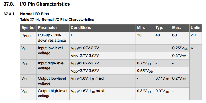
A screen capture from the electrical characteristics section of [Atmel’s SAM D21 datasheet](http://www.atmel.com/Images/Atmel-42181-SAM-D21_Datasheet.pdf)
What about the voltages between .99V and 1.815V? The read behavior is undefined and you are not guaranteed to get an accurate result. That’s one reason why it’s important to make sure that any module you connect to a Tessel input pin provides a high voltage that is between VIH and 3.3V and a low voltage between ground and VIL.
More GPIO example code and information
Output
When acting as a digital output, a pin can be set to one of two states: high (on/1/true) or low (off/0/false). High means the main Tessel board will set that pin to be 3.3V and low means it will set it to 0V.
Digital output is useful for connected hardware that understands simple on/off states. The following code snippet shows how you can set the state of the pin 2 on port A.
const tessel = require('tessel');
const pin = tessel.port.A.pin[2]; // Select pin 2 on port A
pin.output(1);  // Turn pin high (on)
pin.read((error, value) => {
  // Print the pin value to the console
  console.log(value);
  pin.output(0);  // Turn pin low (off)
});
Some examples of using a GPIO pin as an output are simple LEDs and for turning appliances on and off with a relay.
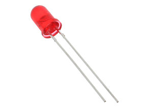
An output pin is perfect for controlling an LED. Image is licensed under the [Creative Commons Attribution-Share Alike 2.0 Generic](http://creativecommons.org/licenses/by-sa/2.0/deed.en) license.
More GPIO example code and information
SPI
Pros: Fast, supports multiple devices on a single bus, allows two-way communication
Cons: Requires at least 3 pins
SPI stands for Serial Peripheral Interface. The SPI protocol allows data to be exchanged one byte at a time between the Tessel and a module via two communication lines. This is great for transferring data like sensor readings or sending commands to a module.
The SPI protocol is known as a Master/Slave protocol, which means that there is always a single master device which controls the flow of communication with one or more slave devices. Think of the master as a traffic cop. It directs all of the connected slave devices so they know when it’s their turn to communicate.
When you are creating modules, the Tessel will always act as the master device, and your custom module will be a slave device.
The SPI protocol requires a minimum of three signal connections and usually has four (this is in addition to the power connections). The following diagram shows the connections (arrows indicate flow of data).
The red lines constitute the shared bus connections used for talking to the slave devices. The green wire is the shared bus connection used by the slaves to talk to the master. The blue line is the chip select for signaling each slave individually.

SCK
This is the clock signal that keeps the Tessel and the module synchronized while transferring data. The two devices need to have a mutual understanding of how fast data is to be transferred between them. This is sometimes referred to as the baud or bitrate. The clock signal provides that reference signal for the devices to use when exchanging data.
Without a clock signal to synchronize the devices, the devices would have no way to interpret the signal on the data lines.
One bit of data is transferred with each clock cycle (see the diagram below).
MOSI
MOSI stands for Master Out Slave In and is the connection used by the Tessel to send data to the module. It’s on this line that the Tessel will encode its data.
MISO
MISO stands for Master In Slave Out and is the connection used by the module to send data to the Tessel.
SS or CS
This line, normally referred to as the Slave Select (SS) or Chip Select (CS) line, is used by the master device to notify a specific slave device that it is about to send data. We normally call it CS, but you may see it either way in datasheets and other references.
When you create a Tessel module which uses the SPI protocol, the CS connection will be handled by one of the GPIO pins on the Tessel port.
The following diagram shows how the various pins in the SPI protocol are toggled to create meaningful data. In this case, the master sends the ASCII character ‘S’, and the slave responds with ‘F’.
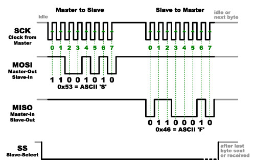
Timing diagram of SPI data exchange. Modified [image](https://dlnmh9ip6v2uc.cloudfront.net/assets/c/7/8/7/d/52ddb2dcce395fed638b4567.png) from Sparkfun is [CC BY-NC-SA 3.0](http://creativecommons.org/licenses/by-nc-sa/3.0/)
Remember that the master initiates all communication. When it is ready, the first thing it will do is pull the CS/SS pin low to let the slave device know that a data transmission is about to begin. The master holds this pin low for the duration of the data exchange as seen in the diagram above.
With the CS/SS pin low, the master will start to toggle the clock pin (SCK) while simultaneously controlling the MOSI to represent the bits of information it wishes to send to the slave. The numbers in green on the diagram above delineate each bit in the byte being transferred.
It sounds complicated, but remember that the Tessel takes care of all of this pin manipulation for you. All you have to do is write some Javascript like this code snippet, which demonstrates the use of the SPI protocol on port A.
'use strict';
const tessel = require('tessel');
const port = tessel.port.A;
const spi = new port.SPI({
  clockSpeed: 4000000 // 4MHz
});

spi.transfer(new Buffer([0xde, 0xad, 0xbe, 0xef]), (error, buffer) => {
  console.log(`buffer returned by SPI slave: <${[...buffer]}>`);
});
More SPI example code and information
I2C
Pros: Only requires 2 pins, multiple devices on a single bus, allows two-way communication
Cons: Devices can have address conflicts, not as fast as SPI
I2C stands for Inter-Integrated Circuit and is pronounced “I squared C”, “I two C” or “I-I-C”. I2C is a protocol that allows one device to exchange data with one or more connected devices through the use of a single data line and clock signal.
I2C is a Master/Slave protocol, which means that there is always a single master device which controls the flow of communication with one or more slave devices.
I2C only requires two communication connections:
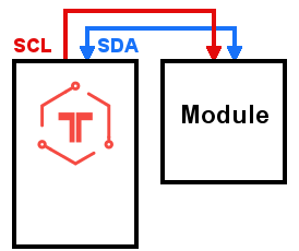
SCL
This is the clock signal that keeps the Tessel and the module synchronized while transferring data. The two devices need to have a mutual understanding of how fast data is to be transferred between them. This is sometimes referred to as the baud or bitrate. The clock signal provides that reference signal for the devices to use when exchanging data. Without a clock signal to synchronize the devices, they would have no way to interpret the signal on the data lines.
SDA
This is the data line used for exchanging data between the master and slaves. Instead of having separate communication lines for the master and slave devices, they both share a single data connection. The master coordinates the usage of that connection so that only one device is “talking” at a time.
Since multiple slave devices can use the same SDA line, the master needs a way to distinguish between them and talk to a single device at a time. The I2C protocol uses the concept of device addressing to coordinate traffic on the data line.
Every single I2C device connected to the Tessel will have an internal address that cannot be the same as any other module connected to the Tessel. This address is usually determined by the device manufacturer and listed in the datasheet. Sometimes you can configure the address through device-specific tweaks defined by the manufacturer. The Tessel, as the master device, needs to know the address of each slave and will use it to notify a device when it wants to communicate with it before transferring data.
Flow of data between Tessel and multiple I2C devices.
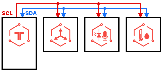
The following diagram illustrates how the SDA and SCL pins are toggled when transferring data with the I2C protocol.

To begin a data transaction, the master creates what is called a start condition by pulling the SDA pin low before the SCL pin.
The master then broadcasts the address of the device it wishes to communicate with by sending each bit of the 7 bit address. Notice the clock signal (SCL) is toggled for each bit. This toggling is how the slaves know when to read each bit of the address so they can determine with which device the master wants to communicate.
Right after the address, the master sends a read/write bit which signals whether it will be sending data to the slave or reading data from the slave.
After broadcasting the address, the master either transmits data to the slave or sends the address of a register (internal storage) on the slave from which it wishes to retrieve data.
Finally, the master will issue a stop condition on the bus by pulling SCL high, followed by SDA.
It’s a little complicated, but the Tessel takes care of all the details for you. Using the I2C pins on port A looks like this:
'use strict';
const tessel = require('tessel');
const port = tessel.port.A;
// This is the address of the attached module/sensor
const address = 0xDE;
const i2c = new port.I2C(address);

i2c.send(new Buffer([0xde, 0xad, 0xbe, 0xef]), (error) => {
  console.log("I'm done sending the data");
  // Can also use err for error handling
})
More I2C example code and information
UART
Pros: Widely supported, allows two-way communication
Cons: Can’t share communication lines, slower than SPI and I2C
UART stands for Universal Asynchronous Receiver/Transmitter and is really just a fancy way of referring to a serial port. It is really easy to understand as it only requires two lines: a transmission line (TX) and a receiving line (RX). The Tessel sends data to connected modules on the TX line and gets data back on the RX line.
TX
Used by the Tessel to send data to the module.
RX
Used by the module to send data to the Tessel.
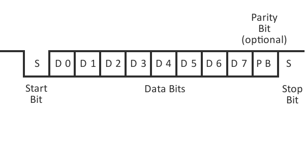
A UART data transmission.
UART transmissions begin with a start bit where the appropriate line (TX or RX) is pulled low by the
Following the data, an optional parity bit is sent, followed by 1 or 2 stop bits, where the sending module pulls the pin high.
For this protocol to work, the sender and receiver have to agree on a few things.
- How many data bits are sent with each packet (5 to 8)?
- How fast should the data be sent? This is know as the baud rate.
- Is there a parity bit after the data, and is it high or low?
- How many stop bits will be sent at the end of each transmission?
When you want to interact with a specific module via UART, the answers to these questions are found in the module’s datasheet. Using that information you can configure the UART in Javascript like this:
'use strict';
const tessel = require('tessel');
const port = tessel.port.A;
const uart = new port.UART({
  dataBits: 8,
  baudrate: 115200,
  parity: "none",
  stopBits: 1
});

uart.write('Hello UART');